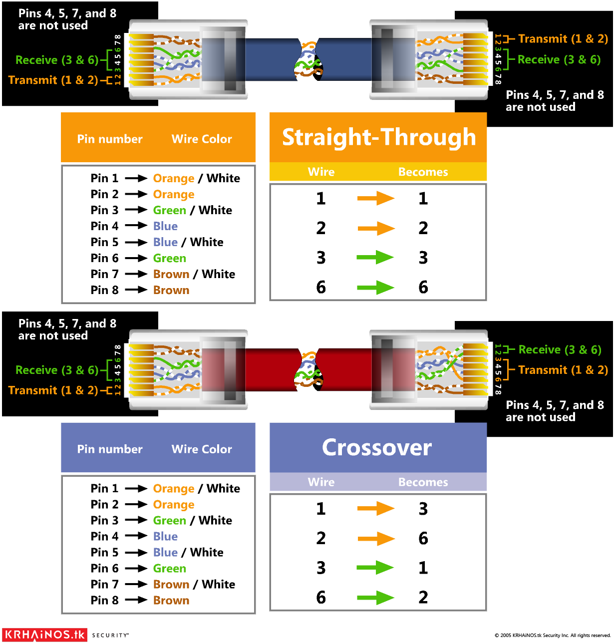
Wiring diagram includes many comprehensive illustrations that show the relationship of assorted products. Another way of remembering the color coding is to simply switch the green set of wires in place with the orange set of wires.
 RJ45 Pinout & Wiring Diagrams for Cat5e or Cat6 Cable in
Usb to cat5 wiring diagram new 1m usb to down angle micro usb cable.

Ethernet cable wiring diagram rj45. When ti comes to built your own reliable network most of the users don't know how to wire ethernet cables to built up a. The hook would be on the back of the image as displayed. The diagram is shown with the hook clip on the underside.
Remember that pin 1 is on the left hand side of the rj45 connector with the clip at the rear. Here a ethernet rj45 straight cable wiring diagram witch color code category 5,6,7 a straight through cables are one of the most common type of patch cables used in network world these days. A wiring diagram is a streamlined standard photographic depiction of an electric circuit.
Bellwire cables may substitute white for orange. Ethernet wiring (8p8c, often incorrectly called rj45). This will insure compliance with ethernet wiring standards.
We hope you enjoyed it and if you want to download the pictures in high quality, simply right click the image and choose save as. The information listed here is to assist network administrators in the color coding of ethernet cables. Crossover ethernet cables are used to connect two devices of the same type together.
Pinout of ethernet 10 / 100 / 1000 mbit (cat 5, cat 5e and cat 6) network cable wiringnowdays ethernet is a most common networking standard for lan (local area network) communication. This article explain how to wire cat 5 cat 6 ethernet pinout rj45 wiring diagram with cat 6 color code , networks have become one of the essence in computer world and for better internet facilities ti gets extremely important to built a good, secured and reliable network. Use this information at your own risk, and.
The rj in rj45 stands for registered jack and is the electrical connection standard that defines how wires are arranged at the end of an ethernet cable. The cable may be utilized to transfer information from 1 apparatus to another. Ponent absolute question and answer thread v 3 ask your.
The diagram to get usb cable can help when there is an issue with it. Ethernet rj45 connection wiring and cable pinout. Ethernet rj45 wiring diagram the image at right shows how to hand wire a commercial rj45 connector for use with an ethernet based network.
September 24, 2018 april 12, 2020. Each part ought to be placed and connected with other parts in particular way. These cables are used to connect different devices over a network, for instance you have to use straight cable if you are connecting.
Cat 5 cable wiring diagram. The cat 5e and cat 6. Most of them use usb cable.
Here is a wiring diagram and pin out: It was introduced commercially in 1989 and became ieee standard 802.3 in 1983. Modular connector plug and jack pin out ethernet cable pin outs:
Specifically, switch the solid green (g)with the solid orange, and In modern structured wiring cat5e or cat6 is commonly used in homes and buildings. Rj45 ethernet cable wiring diagram.
It reveals the components of the circuit as simplified shapes, and the power as well as signal connections in between the devices. It contains instructions and diagrams for different types of wiring methods as well as other products like lights, windows, and so on. The ethernet cable used to wire a rj45 connector of network interface card to a hub, switch or network outlet.
Like you want to connect two routers or two pcs. Recall that there are two standards for the colors in the rj45 specification: Please be aware that modifying ethernet cables improperly may cause loss of network connectivity.
Rj45 colors & wiring guide diagram tia/eia 568 a/b. Otherwise, the structure will not work as it should be. Collection of cat 6 wiring diagram rj45.
Knowledge on recommending elements of usb is going to assist consumer in finding out which component that needs to be adjusted. • another way of remembering the colour coding is to simply switch the green set of wires in place with the orangeset of wires. This article shows how to wire an ethernet jack rj45 wiring diagram for a home network with color code cable instructions and photos.and the difference between each type of cabling crossover, straight through ethernet is a computer network technology standard for lan (local area network).
The jack should have a wiring diagram or designated pin numbers/colors to match up to the color code below. Wiring diagram usb to rj45 2018 wiring diagram for trailer plug. It contains guidelines and diagrams for different types of wiring methods as well as other things like lights, home windows, and so forth.
There are two basic ethernet cable pin outs. There are two standards for ordering the colors of the ethernet cable’s wires with the 8 pinouts on the rj45. In addition, it can link device to a power supply for charging purpose.
 Wiring Diagram Rj45 Crossover Straight And Unbelievable
 How to Make an Network Cable Cat5e Cat6
 RJ45 Plug Wiring per EAITIA T568B Network
 Cat6 RJ45 Jack Wired per EIATIA T568B Standard
 Poe Wiring Diagram Diagrams Schematics At Diagram, Wire
 Rj45 Cat5e Wiring Diagram in 2020 (With images)
 Described here is a simple RJ45 cable tester circuit which
 How To Distinguish T568a And T568b Rj45 Cable
CABLES RJ45/COLORS & CROSSOVER Ingegneria
 Rj45 Wiring Diagram Cat5 Networking basics,
 How To Make An Network Cable Cat5e Cat6 In Rj45
 Rj45 To Rj12 Wiring Diagram Arduino, Usb, Diagram
 RJ45 Diagrama de cableado Electricidad
 Cat 6 Network Cable Diagram Reading Industrial Wiring
 568A And 568B wiring RJ45 standards Computers
 Unique How to Connect Electricity Wires diagram
 New Wiring Diagram for Home Phone Jack diagram
 T568A T568B RJ45 Cat5e Cat6 Cable Wiring Diagram
Komentar
Posting Komentar