Jumped the gauge and it and the gauge went over to the full mark. Marine fuel tank wiring diagram.
 22 Clever Wiring Diagrams For Cars Design Ideas , https
Ford fuel gauge wiring diagram along with s ford trucks forums attachment php attachmentid 52123 stc 1 d 1332807176 as well asstang mustang forums attachments attachment php attachmentid 54945 stc 1 d 1215873264 gif 554001 furthermorevolovets info files ididit steering column wiring diagram awesome radio diagrams with and wheel control also1 bp.

Boat fuel tank gauge wiring diagram. Install the new gauge, reconnect the wiring and turn on the power. We traced back all wires and found some that have been cut and just dont make any sense. Boat building repair and project supplies.
It shows the parts of the circuit as simplified shapes, and the power as well as signal links between the devices. I stuck my head down under the dash and along the underside of the gunnal, and was shocked and afraid at the same time. I'm looking at this hydrasport, as a candidate for more than just this fuel gauge rewire.
Fuel guage does not work, registers empty (full tank of fuel). An electrical fuel gauge can help you. My buddy and i are having trouble tracing down trouble with the fuel systems wiring.
Sometimes we find that the gauge is not the problem and that a wire or a in most circumstances this is actually caused by the fuel sloshing in the tank and. Move to the fuel tank and locate the wire connectors attached to the fuel level indicator plate. 1) +12v when the key is on.
A wiring diagram is a simplified standard pictorial depiction of an electrical circuit. The fuel gauge reads the resistance to ground check the wires on the back of the gauge pink to s terminal and black to g terminal. Direct wired the sending unit to the.
If the gauge then reads full scale, then the problem was with your sender. The fuel gauge should now show the correct fuel level in. When you're out on a boat, you may need to know how much fuel you have left without looking inside the tank.
To test senders, the resistance values are shown at minimum and full gauge scales. “s” for the sender, “g” or “—” for the ground, and “i” for the ignition. If not, unplug the pink wire and connect it to a known good ground like your engine block or the negative terminal on your battery.
Whether the connection to the fuel gauge is a clip connection or a screw connection, spray it with vinyl electrical insulator spray after making the connection. Testing boat analog fuel gauge and boat fuel sending unit. I've seen the boat wiring diagram, but that is showing the gauge end.
Gas tank gage aftermarket fuel tanks for boat for sending unit. The sending unit will ground through the mount screws. 800 x 600 px, source:
How to determine if your boat's fuel sending unit or fuel gauge is not working. Automotive wiring diagram worksheet inspirationa fuel gauge sending. 800 x 600 px, source:
For the fuel gauge, it’s best to remove it from the tank and manually work the float mechanism to see if the gauge then moves. If the gauge does not move, then remove the two wires. Gooddy.org how to wire up a fuel sending unit readingrat net exceptional, size:
Fuel gauge wiring diagram request there are four connections on the gauge itself. In fact, the first thing i do when accessing a fuel gauge or sender problem is ground the sender lead at the sender. Pull the wires far enough away from the fuel tank so that if they were to arc, you would not ignite the fuel.
Dual fuel tank wiring diagram/ help. If it reads full on the gauge, the sender is likely bad or has a bad connection. Wiring a fuel gauge is much the same as wiring any other gauge on your boat:
If the gauge reads zip, the gauge or a wiring fault needs to be addressed. We know the gauge works but unsure if the senders are any good. Check the wiring diagram that comes with the kit and mark the back of the new fuel gauge with symbols for each post:
A unique way to cruise social distance style. Carlplant.me if the image above is not really clear, please click the photo you intend to expand, then you will be required to an additional web page to display a more. Checked the ohms on the sending unit for resistence and it seems to work properly.
How to install a moeller fuel gauge rh jamestowndistributors com water marine fuel sending unit wiring diagram, marine fuel sender unit. Variety of marine fuel gauge wiring diagram. That connection can come from the +12v connection on any other gauge as they are simply daisy chained from one to the next.
Electrical gauges are used when the tank is internal and some distance from where you operate the boat. 26.05.2019 26.05.2019 7 comments on tracker pro guide v16 boat fuel gauge wiring diagram. How to test and replace your fuel gauge sending unit sail magazine customer support moeller marine diagram tank full version hd quality iphonelinux mypapertoy fr ajaxdiagram accademia archi it frequently asked questions s10 gas wiring schooldiagram chamblybad lv 9817 chevy as well boat for atomdiagrams douroapartments reed switch defender ol 5752 sender how to test and replace your… read more »
A switch has been pre wired into the boat from. Wiggle the wires and see if the gauge moves. The fuel tank should be grounded and the sender wire pink should be connected to the sender terminal on the sending unit this is the correct wiring.
One wire comes from the ignition to the instrument, one wire comes from the sensor to the instrument, one wire comes to the instrument light and one wire from the instrument goes to the boat's common ground. The hot terminal on the gauge is for the light. Check the wiring diagram that comes with the kit and mark the back of the new fuel gauge with symbols for each post:
Gas tank sending unit wiring diagram help silvertip and all of you with the good info, thanks a heap. Hydrasport, as a candidate for more than just this fuel gauge rewire.
 Pin de Rodrigo en coche Mecanica automotriz, Auto
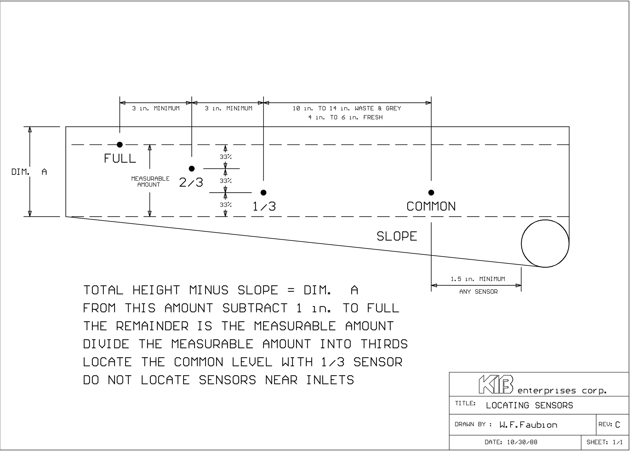 Pin by Randy Oliver on Travel Trailers Diagram, Sensor
 Pin on kc
Combo Fuel System Diagram.JPG (1528×902) Emergency
 1971 Bus Wiring diagram Stuff to Try
 Ford Fuel Pump Wiring Diagram Within Engine repair, Ford
 1968 VW Bus Wiring Diagram Electrical wiring diagram, Vw
 Unique Wiring Diagram for Jet Boat
 Sportsman Gasoline 4000 Watt Portable Generator CARB
Komentar
Posting Komentar